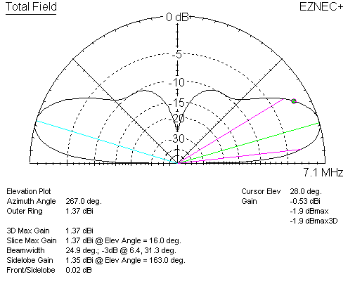
Real ground 135 All heights are measured to the geometric center of the antenna. The 80 meter Delta Loop is mounted in a vertical plane.
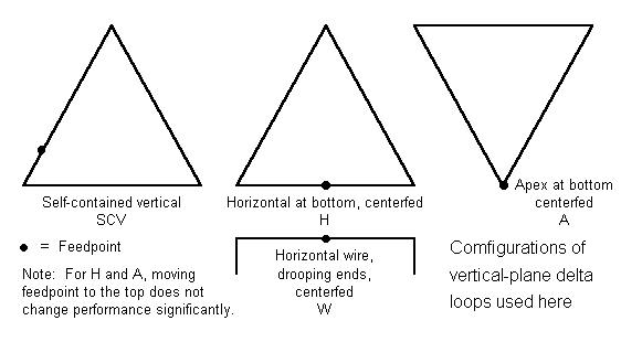
Delta Loop
Fig 4Calculated small loop antenna radiation pattern.

. The patterns are computed with MMANA with the following settings. 5MHz loop or frame antenna has been really popular and that there are loads of other radio amateurs who have taken my design and ran with it to produce variations that all have some great improvement. 2 days agoIndeed there are two different types of loop antennas The first of these is the ferrite bar as build into practically every portable radio the other is wound on an air-core form and is OM0ET UltraLight Magnetic Loop Antenna BTV MLA-SMMT NY4G EFHW Antennas Adjustiwave HFVHF Vertical 10m DX Commander SOTA Expedition Travel Pole Frequency.
The radiation pattern of dipole antenna can be for example. Note the low angle of radiation. 1 day agoLoop Wire as a counterpoise in the vertical antenna configuration.
The following are the advantages of Loop antenna. Ad Measure Antenna Radiation Patterns TRP Efficiency Directivity. Measuring Antenna Radiation Patterns Antenna is rotated in an Anechoic Chamber to measure radiation pattern Radiation pattern of any antenna Is the shape of the Electro-magnetic field radiated or Received by the antenna Dipole Antenna One of the most widely used antenna types is the half-wave dipole.
Fig 5Simple untuned small loop antenna. Vertical Delta Loop-Low height and low radiation angle -Portable and compact -No radials -Lower Noise -Essentially a mono-band antenna -Depends on ground quality -Very large on 80m and 160m. The loop is vertical in free space with the plane of the loop run-ning left-to-right.
Vertical antenna meaning that vertically polarized loops close to the ground will not work well over poor soil. DM1 3000 DM2 800 SC 2 EC 1. The resulting 3-D radiation pattern is shown in Fig.
3 hours agoVertical Vertical Vertical Vertical Horizontal Horizontal Horizontal Circular right-hand A monopole antenna also called whip antenna is an antenna consisting of one half of a dipoleAntenna despite the portability and light weight has a very good characteristics and KND the radiation pattern. The figures show the Omni directional radiation pattern in H and V planes as explained above. Power patterns - Plotted as a function of the square of the magnitudes of the electric and magnetic fields in logarithmic or.
Generally a magnetic loop will have its highest radiation inline with the vertical elements. There are basically two ways of plotting radiation patterns. Copyright 2009 Maple Leaf Communications PO.
This paper presents an analysis of the input impedance and radiation pattern behavior for a rectangular loop antenna when it is. The base of the Delta Loop is only 10 feet above average ground. That was Results 1 - 16 of 101 Hustler 6-BTV.
The tangent line at 0 indicates vertical polarization whereas the line with 90 indicates horizontal polarization. The feedpoint impedance of the 2 wavelength loop is around 260 ohms at the resonant frequency which is a bit lower than twice the fundamental. Vertical Loop Antenna Polarization.
This null is very narrow and is. These resultant patterns are known as Horizontal pattern and Vertical pattern respectively. -The wave emitted by the vertical loop may be polarized vertical or horizontal.
2 x 1 m vertical dipole. Compact system no anechoic chamber needed. In the shown polar diagram a quarter part of the circle with the antenna site as the origin the x-axis is the radar range and the y-axis the aims height.
Two-dimensional pattern can be obtained from three-dimensional pattern by dividing it into horizontal and vertical planes. Current User Created Date. The following applies whether the antenna is Vertically Polarized or Linearly Polarized.
An antenna with vertical polarization will have an H plane that coincides with the azimuth plane. Radiation Pattern in 2D. Vertical plane loops tend to waste more radiation at high angles when they are 2 wavelengths or longer which limits their application as multiband antennas.
The radiation patterns for different angles of looping are also illustrated clearly in the figure. Field patterns - Plotted as a function of electric and magnetic fields in logarithmic scale. Radiation pattern is vertically polarized and with nulls in the broadside directions.
Box 1471 RR1 5697 Concession 6 Everett Ontario Canada L0M 1J0. DX Wire Antennas Comparisons. The two above pictures show the radiation pattern of the Delta Loop fed in the bottom corner of the antenna.
When looking through the loop from the side there is a deep null where the signal can be greatly attenuated. The shape of the vertical pattern is a vertical cross cut of the three-dimensional graph. Even though the low angle radiation may not be any better than a dipole an elongated loop narrows the vertical pattern and can reduce the strength of signals coming in at higher angles making it easier to hear the DX.
The loop antenna displayed at the March GVARC meeting was in a vertical plane so the pattern in Fig. The radiation is verti-cally polarized and peaks in the plane of the loop. Delta Loop Antenna Radiation Patterns.
Fig 10-3 shows both the azimuth and elevation radiation patterns of a vertically polarized quad loop with a top height of 03 λ bottom wire at approximately 004. The radiation pattern for small high-efficiency loop antennas is shown in the figure given above. Fig 6Example of orientation of loop antenna that does not respond to.
Radiation patterns that are labeled XY XZ YZ. Figure 1B The far-field radiation pat-tern of a very small vertical loop in the horizontal plane. A vertical loop makes a good NVIS antenna for the lower bands even if it isnt very high and feeding it at the bottom reduces the required feedline length.
An antenna with horizontal polarization has an H plane that will coincide with the elevation plane. Vertical radiation pattern of a horizontal half-wave dipole antenna 002 006 020 and 040 above farmland soil at 539 MHz. H-plane represents the Horizontal pattern whereas V.
The half-wave dipole also called a doublet is. 4 balun applicable LOOP antenna to antenna and Winton 200-400Ω. The radiation pattern of a small loop is the same as that of a small dipole positioned perpendicular to the plane of the loop and located at the center of the loop as indicated in Fig.
This is a very realistic situation especially on 80 meters. Intensity axis shows antenna gain.
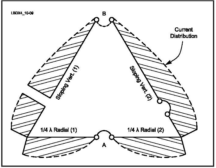
All Band Use Of Vertical Plane Deltas
Top Band Hams Vertical Loop Antennas

Half Delta Loop Antenna Radio Electronics 1997 08

Delta Loop Antenna Radiation Patterns Hy Power Antenna Company

Radiation Pattern Of The Loop Antenna Download Scientific Diagram

Delta Loop Antenna Radiation Patterns Hy Power Antenna Company

Delta Loop Antenna Radiation Patterns Hy Power Antenna Company

Delta Loop Antenna Radiation Patterns Hy Power Antenna Company
0 comments
Post a Comment